


Blog
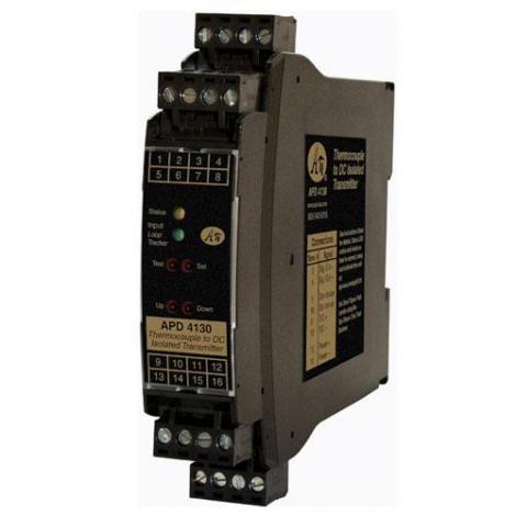
How Far Can a 4-20 mA Temperature Transmitter Run? Understanding Loop Resistance and Cable Distance
Accurate temperature readings are only useful if the signal survives the trip from the sensor back to your control room. In large plants, that trip can be hundreds or even thousands of feet, and it's one of the most common questions we hear at MOD-TRONIC: how far can I actually run a temperature transmitter before the signal breaks down?
The good news is that a 2-wire, 4-20 mA transmitter is built for distance. The better news is that there's a simple way to calculate exactly how far you can go before you run into trouble. In this article we'll walk through what limits the distance, the formula that tells you your maximum, and a real-world example you can apply to your own installation.
Why RTD Signals Fade Over Distance
A bare RTD sends a low-level resistance signal, and resistance signals degrade as wire length increases. The lead wires themselves add resistance, and that added resistance shows up as an apparently higher temperature reading that drifts with the ambient conditions around the cable. Three- and four-wire RTD circuits help compensate, but they become impractical and expensive once you're spanning more than a few hundred feet.
This is exactly why temperature transmitters exist. Instead of sending a fragile resistance signal, a transmitter converts the RTD reading into a 4-20 mA current signal right at the sensor. Because the current in a series loop is the same at every point in that loop, lead resistance no longer changes your reading. The signal can travel a very long way without losing accuracy.
But "a very long way" is not "infinitely far." There is a limit, and that limit has a name: loop resistance.
The Real Limit: Loop Resistance
Every 4-20 mA current loop has a maximum amount of resistance it can drive. The transmitter needs a minimum voltage across its own terminals to operate, and everything else in the loop — the load resistor, the wire, and any additional devices — consumes part of the supply voltage. Add up too much resistance and the supply can no longer push a full 20 mA through the loop. When that happens, your high-end readings flatten out and your measurement is no longer trustworthy.
The maximum resistance your loop can tolerate is given by a straightforward formula:
R(loop max) = (V supply − V transmitter min) / 0.023 A
The 0.023 A (23 mA) figure reflects the small amount of headroom above the 20 mA full-scale signal that most transmitters draw. Everything comes down to how much voltage you start with and how much the transmitter needs to keep running.
A Worked Example
Suppose you're powering a transmitter that operates on 8.0 to 30 VDC from a 24 VDC supply. Plugging in the numbers:
R(loop max) = (24 V − 8 V) / 0.023 A = 696 Ω
That 696 ohms is your total budget for the load resistor plus all of your wire. As a rule of thumb, we recommend designing to about 80% of that maximum to leave a safety margin for temperature swings, supply variation, and aging components. That brings your working budget down to roughly 557 ohms.
Now subtract your load resistor. A common value is 250 Ω, which conveniently turns a 4-20 mA signal into a 1-5 VDC input for your PLC or indicator. That leaves about 307 ohms for the wire itself — and remember, current has to travel out to the sensor and back, so you're paying for the resistance of both conductors.
Turning Ohms Into Feet
Once you know your wire budget in ohms, converting to distance is just a matter of the wire gauge you've chosen. Thinner wire has more resistance per foot, so heavier gauge cable buys you more distance. Here are approximate resistances for common copper conductors:
- AWG 18 — about 6.5 Ω per 1,000 ft (per conductor)
- AWG 20 — about 10 Ω per 1,000 ft (per conductor)
- AWG 22 — about 16 Ω per 1,000 ft (per conductor)
- AWG 24 — about 26 Ω per 1,000 ft (per conductor)
Using AWG 22 wire from our example, each 1,000 feet of cable adds roughly 32 ohms once you account for the round trip out and back. Dividing our 307-ohm wire budget by that figure gives about 9,500 feet — nearly 1.8 miles of cable on a single 24 VDC loop. Step up to a heavier gauge or a higher supply voltage and you can push even farther.
That's the headline worth remembering: a properly designed 4-20 mA temperature loop can comfortably run well over a mile without losing a bit of accuracy.
What Shortens Your Maximum Distance
Distance isn't the only thing competing for your resistance budget. Before you finalize a design, keep these factors in mind:
- Supply voltage. A higher supply voltage directly increases your loop-resistance budget. Moving from 24 V to a higher regulated supply is often the easiest way to gain distance.
- Load resistor value. A larger load resistor eats into the wire budget. Use the smallest value that still produces a usable input voltage for your receiving device.
- Multiple devices in the loop. Every indicator, recorder, or additional load resistor placed in series adds resistance. Total up all of them plus the wire, and the sum must stay under R(loop max).
- Wire gauge. Heavier (lower AWG number) wire has less resistance and extends your range, at a modest increase in cost and cable weight.
Distance Isn't the Only Reason to Use a Transmitter
It's worth noting that long cable runs also tend to be electrically noisy runs. The same 4-20 mA signal that shrugs off lead resistance also resists electrical noise from nearby motors, drives, and lighting, especially when carried on shielded, twisted-pair cable. So even in installations that aren't especially long, a transmitter often pays for itself in cleaner, more reliable readings. Whether you need a DIN rail mount transmitter for a control panel or a head mount transmitter that installs right at the sensor, the loop-resistance math works the same way.
Let MOD-TRONIC Help You Size Your Loop
Every installation is a little different, and choosing the right transmitter, supply voltage, load resistor, and cable for your distance can be the difference between a system that just works and one that constantly fights noise and drift. As the largest authorized MINCO stocking distributor in the world, MOD-TRONIC keeps thousands of temperature sensors and RTDs and temperature transmitters on the shelf, and our experienced staff is ready to help you specify the right combination for your application.
Have a long run to plan or a signal problem to solve? Give us a call at 1-800-794-5883 or request a quote through our website, and we'll help you get it right the first time.



